Open inspector mode - F12 or CTRL+SHIFT+I
then CTRL+SHIFT+P
and type screenshot - and select Capture ful size screenshot.

Open inspector mode - F12 or CTRL+SHIFT+I
then CTRL+SHIFT+P
and type screenshot - and select Capture ful size screenshot.
I tried to take a screenshot from a .mkv video and it crashes every time though it works fine with normal mp4.
To fix it disable hardware acceleration in codecs.
Go to Preferences - Input/Codecs - Hardware-accelerated decoding -
Change from Automatic to Disabled.
Try again. It worked for me.

Once you install DaVinci you get a message that no suported video cards are detected and something about no media storage.
You need to install video and opencl drivers.
SANE_DEBUG_DLL=3 scanimage -L
load: dlopen() failed (libusb-0.1.so.4: cannot open shared object file: No such file or directory)
To fix it:apt search --names-only libusb-0.1rezult: libusb-0.1-4/stable 2:0.1.12-32 amd64 sudo apt install libusb-0.1-4 Debian has the largest package library of software.
It uses a package format .deb that are installed by the dpkg app.
In order to manage dependencies and download automatically there is apt (Advanced Packaging Tool).
Synaptic is a graphical package management tool based on GTK+ for apt.
Apt commands in the console.
You can use synaptic as a GUI for apt.
apt autoremove packagename --purge - remove binaries, config, user data and dependencies - complete uninstall
apt list --installed | grep packagename - check if you have some package installed
Note: - purge only removes system wide configuration from the /etc folder.
It does not remove user profiles that are stored in the home folder .config and .cache folders
To remove 32 bit architecture packages and remove source repositories
sudo apt-get purge `dpkg --get-selections | grep ":i386" | awk '{print $1}'`
dpkg --remove-architecture i386
dpkg --print-foreign-architectures
https://ninite.com/ - package repository for windows.
Pin 1 (sensor led) - 150ohm resistor to vcc 5v
Pin 6 - vcc 5v
Pin 2 - to gnd
Pin 4 - to gnd
Pin 3 - input led - connect to a digital pin on arduino.
Note according to datasheet the input (drive) led is actually the base of a transistor connected to GND and not the actual led. So when we set the digital pin to HIGH we connect the led to GND and stop it.
To turn the led on we have to set the digital pin to LOW.
Pin 5 - output- connect to analog pin on arduino A0-A5

Datasheet: https://global.sharp/products/device/lineup/data/pdf/datasheet/gp2y1010au_e.pdf
Connect Pin 3 lets say to DIGITAL 3.
We set in void() function --> pinmode(3, OUTPUT);
// one read
digitalWrite(ledPin, LOW); // power on the LED
delayMicroseconds(280); // Wait 0.28ms according to datasheet
output_voltage = analogRead(3); // read output
delayMicroseconds(40); // wait 0.040 ms according to datasheet
digitalWrite(ledPin, HIGH); // turn the LED off
output_voltage = (3.33 / 4096) * output_voltage; // max 3.6v
delayMicroseconds(9760);
Note: i used a chinese clone from wavgate and althout it says it has an atmega 328p chip - the analog line read 4064 when connected to the 3.3v line - so that means a 12bit ads with 3.33v internal reference.
If you have the normal 5v 10bit 1024 resolution ads - change above to 3.33/4096 to 5/1204 .
If you are not sure what ads bits you have, connect the 3.3 and 5 lines to A0 for example and read with analogRead and see what result you get.
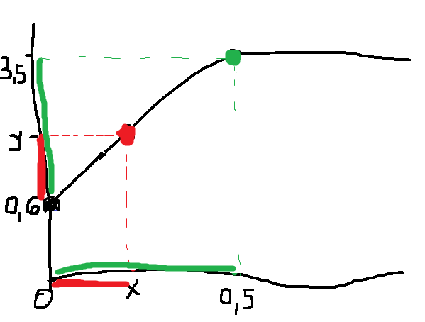
Next we have to convert the voltage to dust density according to the graph offered in the datasheet.
We have from the graph and datasheet info:
Output voltage at no dust 0.6v - 0 mg/m3 dust - given in the datasheet
And the graph intersect at 3.5v - 0.5 mg/m3 dust - you can see it on the graph clearly
With two points we can make a formula.
y-0.6 = x-0
3.5-0.6 = 0.5-0
y-0.6 3.5-0.6
------- = ----------
x-0 0.5-0
x = 0.5(y-0.6) / (3.5-0.6)
x = (y-0.6)*0.5/2.9 = (y-0.6)*0.17 = 0.17*y - 0.6*0.17 = 0.17y-0.1
Note: the sensor it is not very exact, as in the datasheet it says voltage at no dust is typical 0.6V but can go from 0.1V to 1.1V
if(output_voltage>0.6) {
dust_density = (0.1724 * output_voltage) - 0.1;
dust_density *= 1000;
}
There you go.
Because the sensor output fluctuates a lot and it is not stable, i like to make an average of around 100 reads (129 in the code below) or about one second - one read takes 10ms - so the output its a bit more stable.
Next is full code that shows result on and a lcd screen or on the serial console.
#include "LiquidCrystal_I2C.h"
LiquidCrystal_I2C lcd(0x27,20,4);
#define dustPin A0
#define ledPin 2
void setup() {
lcd.init(); // initialize the lcd
lcd.backlight();
lcd.clear();
Serial.begin(115200);
while (!Serial) delay(100);
Serial.println("GP2Y1010AU0F Sensor demo");
pinMode(ledPin,OUTPUT);
}
int i =0;
float sum =0;
void loop() {
float output_voltage =0;
float dust_density = 0;
// 100 samples medie - 1 reading per second
// one read
digitalWrite(ledPin, LOW); // power on the LED
delayMicroseconds(280); // Wait 0.28ms according to DS
output_voltage = analogRead(dustPin);
delayMicroseconds(40);
digitalWrite(ledPin, HIGH); // turn the LED off
output_voltage = (3.33 / 4096) * output_voltage; // max 3.6v
delayMicroseconds(9760);
if(output_voltage>0.6) {
dust_density = (0.1724 * output_voltage) - 0.1;
dust_density *= 1000;
}
else dust_density = 0;
sum = sum + dust_density;
i++;
if(i==129*2) {
dust_density = sum / i;
i=0;
sum =0;
lcd.setCursor(0,0);
lcd.print("Dust: ");
lcd.setCursor(6,0);
lcd.print(dust_density);
lcd.print("ug/m3");
/*
Serial.print(",\tDust Density = ");
Serial.print(dust_density);
Serial.println(" ug/m3");
*/
}
}

Open Arduino IDE go to File -> Preferences and add the link
https://dl.espressif.com/dl/package_esp32_index.json, http://arduino.esp8266.com/stable/package_esp8266com_index.json
Then go to boards, search and install esp32.
When you upload the code if you get
Failed to connect to ESP32: Timed out waiting for packet header
just press/hold the boot button - when it shows connecting... ___ ..... ____ .....
ESP32 Pinout

Meditation and bio-feedback.
HRV - heart rate variability
On an ECG - electrocardiogram - you get the letters P Q R S T.
The time between two R, noted as R-R is HRV.
During relaxation the parasympathetic nervous system dominates, heart bpm drops and HRV increases
During stress the sympathetic nervous system dominates, heart bpm increases and HRV decreases
If you are chronically stressed or injured etc the body will stay in a sympathetic mode to sustain recovery even while resting. This is consuming for the body and you should not do any stressful activities like training, tough decisions etc. that like overcome the body's ability to compensate and it will trow you out of balance and in a bad state of health.
Hence the need to read your morning HRV so you know how your body is doing and how you continue your day.
Sensors:
- HearthMath Inner Balance sensor: many reviews on amazon say the sensor's quality is not reflected by its price which is around 160$ + shipping
- Polar H7/H9 or H10 - H10 being the best for accuracy - most easy to find and buy locally ~ 100$
- CorSense from the maker of the app https://elitehrv.com/ - 165$ - but expensive outside of the US ( around 200$ in europe with added vat) - the most convenient one to use
Polar H7 and H9 vs Poalr H10
You can see in the above image, the H10 has the same metal rounded electrode that is crimped to the connector, but also another rectangular metal band behind it that acts as a shield connected to ground to prevent exterior interference.
Note: i bought an spare chest strap from aliexpress that it is rated as a replacement for the H10 but it only has the main electrode and no shielding - so it is an equivalent to the H7/H9 soft strap.
“The extra interference-preventing electrodes on the strap make it extremely sensitive to your heart’s electrical signals, providing maximum precision for heart rate readings and eliminating interference.”


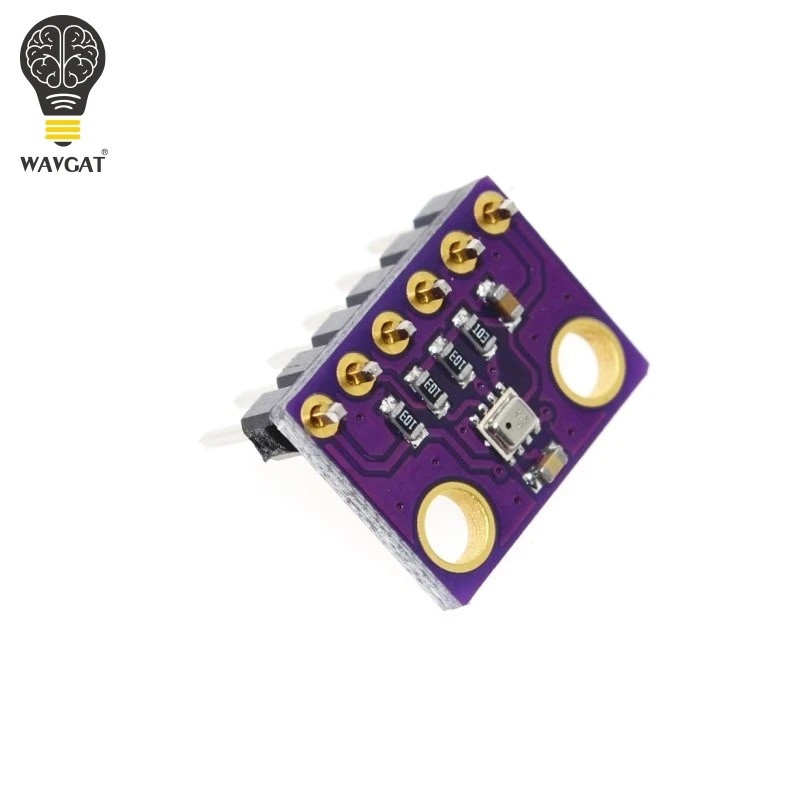
#include <Adafruit_Sensor.h>
#include <Adafruit_BME280.h>
Adafruit_BME280 bme; // I2C
void setup()
{
bool status;
status = bme.begin();
}
void loop() {
float temp = bme.readTemperature(); // celsius
float humidity = bme.readHumidity(); // read humidity
float altitude = bme.readAltitude(1013.25);// read altitude SEA LEVEL PRESSURE_HPA (1013.25)
float pressure = bme.readPressure() / 100.0F; // read pressure
delay(5000);
}
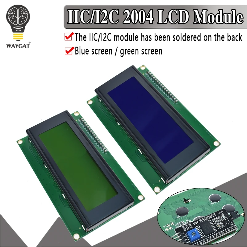
#include <LiquidCrystal_I2C.h>If you have more devices on the I2C buss you can change the address by soldering the A0, A1 OR A2 connection on the PCF8574T board.
LiquidCrystal_I2C lcd(0x27,20,4); // set the LCD address to 0x27
void setup()
{
lcd.init(); // initialize the lcd
lcd.backlight();
lcd.clear();
lcd.setCursor (0,3); // first parameter its the line 0,1,2,3 - second character position 0-20
lcd.print("Hello World");
}
void loop() {
}


