Showing posts with label Electronics. Show all posts

Tuesday, September 20, 2022

Drone project

Battery LiPo

The voltage in LiPo (Lithium Polymer) batteries is determined based on the number of cells they have and we can easily identify this by referring to the "S" count. Each LiPo cell is rated at 3.7v so a 2S LiPo means it's a 2 cell battery and 7.4v, a 3S is 11.1v, 4S is 14.8v and 6S is 22.2v.

Motor

 2306 2555KV

Firmware - https://ardupilot.org/

Saturday, August 13, 2022

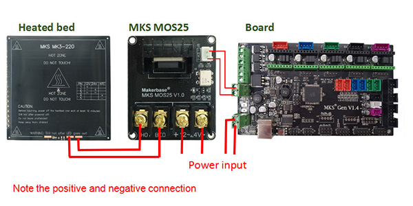
Heatbed MOSFET 3d printer

  HA210N06 -  210A 60V N-Channel MOSFET - datasheet

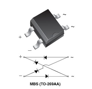
MB6S - Bridge Rectifier - it corrects reverse polarity to MOSFET gate - so you don't burn it. With this on the board you can connect the wire without worrying about polarity. - datasheet

EL 817 C915 - PHOTOCOUPLER - datasheet

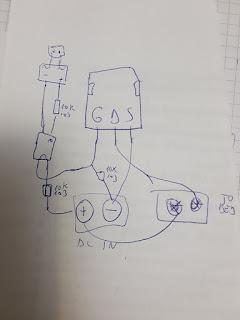
The way it should be used it is like this:

MOSFET 25A

Voltage limits of the circuit

On the drive signal - the limiting factor is the optocoupler max forward current of 60ma. We have a 10k resistor so a maximum of 600v - that also coresponds to the bridge rectifier max voltage. So we have no maximum real limit but we have a problem with the minimum voltage.

The optocoupler support maximum 35v on the output side collector-emitter. The MOSFET takes 25v on the gate-source side, and it has a voltage divider of 50% so it takes a max of 50v DC IN but we have the 35v limit on the optocoupler. So 35v is maximum DC IN.

optocoupler input is connected through a 103 resistor - 10k - after it passes through the bridge rectifier first. If you are using a microcontroller with 3.3v logic voltage it will not open. You need to replace the 10k with 1k 102 resistor.


Friday, May 21, 2021

3 PRONG ROCKER SWITCH

It has 3 legs marked 1, 2 (c - for common) and 3 (+/-) for light.

The rocker switch moves a metal arm between contact 2 and 1 on and off.
The 2 (c) is always on, only contact on pin 1 is on / off.

Pin 3 can be connected to the opposite polarity then what you chose to switch so the light turns on.

Note some have a led connected and same have a indicator glass bulb for 220v.

Saturday, January 9, 2021

Sharp GP2Y1014AU0F air quality with arduino

Pin 1 (sensor led) - 150ohm resistor to vcc 5v
Pin 6 - vcc 5v

Pin 2 - to gnd
Pin 4 - to gnd

Pin 3 - input led  - connect to a digital pin on arduino.
Note according to datasheet the input (drive) led is actually the base of a transistor connected to GND and not the actual led. So when we set the digital pin to HIGH we connect the led to GND and stop it.
To turn the led on we have to set the digital pin to LOW. 
Pin 5 - output- connect to analog pin on arduino A0-A5

Datasheet: https://global.sharp/products/device/lineup/data/pdf/datasheet/gp2y1010au_e.pdf

Connect Pin 3 lets say to DIGITAL 3.

We set in void() function --> pinmode(3, OUTPUT);

// one read
digitalWrite(ledPin, LOW); // power on the LED
delayMicroseconds(280); // Wait 0.28ms according to datasheet
output_voltage = analogRead(3); // read output
delayMicroseconds(40); // wait 0.040 ms according to datasheet
digitalWrite(ledPin, HIGH); // turn the LED off
output_voltage = (3.33 / 4096) * output_voltage; // max 3.6v
delayMicroseconds(9760);

Note: i used a chinese clone from wavgate and althout it says it has an atmega 328p chip - the analog line read 4064 when connected to the 3.3v line - so that means a 12bit ads with 3.33v internal reference.
If you have the normal 5v 10bit 1024 resolution ads - change above to 3.33/4096 to 5/1204 .

If you are not sure what ads bits you have, connect the 3.3 and 5 lines to A0 for example and read with analogRead and see what result you get.

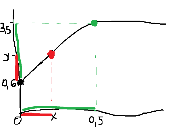
Next we have to convert the voltage to dust density according to the graph offered in the datasheet.

We have from the graph and datasheet info:
Output voltage at no dust 0.6v - 0 mg/m3 dust - given in the datasheet
And the graph intersect at 3.5v - 0.5 mg/m3 dust - you can see it on the graph clearly
With two points we can make a formula.

y-0.6 = x-0
3.5-0.6 = 0.5-0

y-0.6      3.5-0.6 
------- = ----------
x-0          0.5-0

x = 0.5(y-0.6) / (3.5-0.6)
x = (y-0.6)*0.5/2.9 = (y-0.6)*0.17 = 0.17*y - 0.6*0.17 = 0.17y-0.1

Note: the sensor it is not very exact, as in the datasheet it says voltage at no dust is typical 0.6V but can go from 0.1V to 1.1V

if(output_voltage>0.6) {
    dust_density = (0.1724 * output_voltage) - 0.1;
    dust_density *= 1000;
}

There you go.
Because the sensor output fluctuates a lot and it is not stable, i like to make an average of around 100 reads (129 in the code below) or about one second - one read takes 10ms - so the output its a bit more stable.
Next is full code that shows result on and a lcd screen or on the serial console.


#include "LiquidCrystal_I2C.h"
LiquidCrystal_I2C lcd(0x27,20,4);

#define dustPin A0
#define ledPin 2

void setup() {

lcd.init(); // initialize the lcd
lcd.backlight();
lcd.clear();

Serial.begin(115200);
while (!Serial) delay(100);

Serial.println("GP2Y1010AU0F Sensor demo");
pinMode(ledPin,OUTPUT);

}

int i =0;
float sum =0;

void loop() {

float output_voltage =0;
float dust_density = 0;

// 100 samples medie - 1 reading per second
// one read

digitalWrite(ledPin, LOW); // power on the LED
delayMicroseconds(280); // Wait 0.28ms according to DS
output_voltage = analogRead(dustPin);
delayMicroseconds(40);
digitalWrite(ledPin, HIGH); // turn the LED off
output_voltage = (3.33 / 4096) * output_voltage; // max 3.6v
delayMicroseconds(9760);

if(output_voltage>0.6) {
dust_density = (0.1724 * output_voltage) - 0.1;
dust_density *= 1000;
}
else dust_density = 0;

sum = sum + dust_density;
i++;
if(i==129*2) {
dust_density = sum / i;
i=0;
sum =0;
lcd.setCursor(0,0);
lcd.print("Dust: ");
lcd.setCursor(6,0);
lcd.print(dust_density);
lcd.print("ug/m3");

/*
Serial.print(",\tDust Density = ");
Serial.print(dust_density);
Serial.println(" ug/m3");
*/

}
}


Wednesday, November 4, 2020

ESP32 ARDUINO


Open Arduino IDE go to File -> Preferences and add the link

https://dl.espressif.com/dl/package_esp32_index.json, http://arduino.esp8266.com/stable/package_esp8266com_index.json

Then go to boards, search and install esp32.

When you upload the code if you get 

Failed to connect to ESP32: Timed out waiting for packet header

just press/hold the boot button - when it shows connecting... ___ ..... ____ .....

ESP32 Pinout


Saturday, November 30, 2019

Air quality PM sensors comparison for arduino

Best accuracy sensor:
( note that it works under 70% humidity depending on what weather conditions you have where you life)


The Nova SDS011 - also recommenced by the https://luftdaten.info/ project


Price: 17$
Official website: http://www.inovafitness.com/en/a/chanpinzhongxin/95.html
Buy from aliexpress: http://s.click.aliexpress.com/e/Nz5SXZBE

Connections for code:
-connect pin TXD on SDS011 to pin 2 in section (Digital PWM) on arduino (it will act as RX on arduino)
-connect pin RXD on SDS011 to pin 3 in section (Digital PWM) on arduino (it will act as TX on arduino)
-5v and gnd - same

Arduino Code: - it will print both to a i2c lcd display and serial console

#include "LiquidCrystal_I2C.h"
#include "SoftwareSerial.h"
SoftwareSerial mySerial(2, 3); 

// Global Variables
static unsigned char buf[7], buffSDS[25];
unsigned int PM2_5,PM10=0;

LiquidCrystal_I2C lcd(0x27,20,4); 

void setup() {
  // put your setup code here, to run once:
  lcd.init();                      // initialize the lcd 
  lcd.backlight();
  lcd.clear();

  
  // Read SDS011 on Serial 
  mySerial.begin(9600);  // 
  mySerial.setTimeout(200);
  //mySerial.readBytesUntil(0xAB,buffSDS,20); // read serial until 0xAB Char received

  // Serial Monitor
  Serial.begin(115200);  


}

void loop() {
  // put your main code here, to run repeatedly:
  // Read SDS011
  mySerial.readBytesUntil(0xAB,buffSDS,20);

  // Serial monitor, print the HEX bytes received in buffSDS
//Serial.write(buffSDS,10);

for ( int8_t i=0; i<10 ; i=i+1 )
  {
  Serial.print( buffSDS[i],HEX);
  Serial.print(" ");

  }
Serial.println("");

  
PM2_5 = ((buffSDS[3]*256)+buffSDS[2])/10; // extract PM2.5 value
Serial.print("PM2.5: ");
Serial.println(PM2_5);

lcd.setCursor(0,0);
lcd.print("PM2.5: ");
lcd.print(PM2_5);


PM10 = ((buffSDS[5]*256)+buffSDS[4])/10; // extract PM10 value
Serial.print("PM10: ");
Serial.println(PM10);
lcd.print((char)228);
lcd.print("g/m3");

lcd.setCursor(0,1);
lcd.print("PM10: ");
lcd.print(PM10);
lcd.print((char)228);
lcd.print("g/m3");


delay(500);
}

The sensor has 8000 hours of usage and outputs data every second. In order to use it for longer time you have to use the sleep and wake up vis serial.

Use this library : https://github.com/ricki-z/SDS011
It also has support for hardware serial connection for the esp32 which does not have software serial.

Check example in the library.


Plantower
Official website: http://www.plantower.com/en/content/?108.html

https://airly.eu/en/ - a project by Philips in witch they use the Plantower PMS5003
You can see the sensor and the insides of their sensor here:
https://www.youtube.com/watch?v=FREADCgdq2M

Plantower PMS5003

Buy the Plantower PMS5003 from aliexpress: http://s.click.aliexpress.com/e/tb2qOLXK
Price: 12-13$


Popular Pm monitors on the market and what sensors they use:

Laser Egg - uses Plantower PMS3003


AirVisual Node : proprietary PM sensorSenseAir S8 - for CO2


Additional resources:

http://aqicn.org/sensor/

https://www.mysensors.org/build/dust

Wednesday, November 20, 2019

Program Arduino Mini Pro 3.3/5V with Arduino Uno


Connect RST pin to GND on Arduino Uno - to bypass the UNO's bootloader

Connect 5V or 3.3V to VCC on Mini
Connect GND to GND on Mini
Connect TX to TX
Connect RX to RX

Select in the Arduino IDE -> Tools -> Board -> Arduino Pro or Pro Mini
Select in the Arduino IDE -> Tools -> Board -> Processor -> 3.3V 8Mhz or 5V 16Mhz
Select in the Arduino IDE -> Tools -> Port

Select File->Examples ->Basics->Blink and press Upload button
When uploading appears in the Arduino IDE press the RESET button on the mini.
When you press the RESET button you should see the rx,tx lights on the uno start to blink fast for a short time - the sketch it is being uploaded.

The led on the Mini Pro should start blinking at one second.
DONE. ENJOY.

Tuesday, November 19, 2019

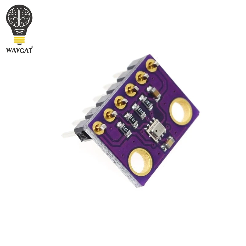
Bosch BME280 sensor with arduino for temp humidity and pressure


Buy sensor for here: http://s.click.aliexpress.com/e/KY9P6WRm


Arduino Libraries Required:
Adafruit_Sensor.h
Adafruit_BME280.h

Go to Tools -> Manage Libraries :
search for bme280 and select the adafruit one, and install all.

Wire connections:
- 5V and GND to coresponding
- the marked ones SDA, SCL on the end of the digital pins
- or the analog pins A4 (SDA) A5 (SCL)

Arduino Code:

#include <Adafruit_Sensor.h>
#include <Adafruit_BME280.h>
Adafruit_BME280 bme; // I2C
void setup()
{
    bool status;
    status = bme.begin();
}
void loop() {
float temp = bme.readTemperature();   // celsius
  float humidity = bme.readHumidity();  // read humidity
  float altitude = bme.readAltitude(1013.25);// read altitude  SEA LEVEL PRESSURE_HPA (1013.25)
  float pressure = bme.readPressure() / 100.0F; // read pressure
delay(5000);

}

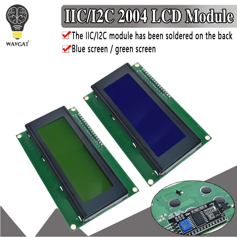
Display 2004A generic 4 line 20 characters display with PCF8574T expander


4 line display with PCF8574T -  I/O expander for I2C-bus -  two-wire bidirectional (serial clock (SCL), serial data (SDA))

Arduino Library required: LiquidCrystal_I2C.h
Put the files in Documents -> Arduino -> libraries

Tip: also buy a case for the display, it stands up and its easy to read: http://s.click.aliexpress.com/e/lqzxEDeo

Wire connections:
- 5V and GND to corresponding
- the marked ones SDA, SCL on the end of the digital pins
- or the analog pins A4 (SDA) A5 (SCL)

Arduino Code:

#include <LiquidCrystal_I2C.h>
LiquidCrystal_I2C lcd(0x27,20,4);  // set the LCD address to 0x27
void setup()
{
  lcd.init();                      // initialize the lcd
  lcd.backlight();
  lcd.clear();
 lcd.setCursor (0,3);   // first parameter its the line 0,1,2,3 - second character position 0-20
 lcd.print("Hello World");
}
void loop() {
}
 If you have more devices on the I2C buss you can change the address by soldering the A0, A1 OR A2 connection on the PCF8574T  board.


To display a special character : lcd.print((char)228);

Contract and Backlight
- In case you don't see nothing on the screen, use a screwdriver and adjust the blue potentiometer on the back.
- The backlight on/off is controlled by the jumper
- jumper in place: backlight on
- jumper removed: backlight off

The backlight can also be controlled with software.
Use  lcd.backlight(); to turn it on and lcd.noBacklight(); to turn it off.