Pin 1 (sensor led) - 150ohm resistor to vcc 5v
Pin 6 - vcc 5v
Pin 2 - to gnd
Pin 4 - to gnd
Pin 3 - input led - connect to a digital pin on arduino.
Note according to datasheet the input (drive) led is actually the base of a transistor connected to GND and not the actual led. So when we set the digital pin to HIGH we connect the led to GND and stop it.
To turn the led on we have to set the digital pin to LOW.
Pin 5 - output- connect to analog pin on arduino A0-A5

Datasheet: https://global.sharp/products/device/lineup/data/pdf/datasheet/gp2y1010au_e.pdf
Connect Pin 3 lets say to DIGITAL 3.
We set in void() function --> pinmode(3, OUTPUT);
// one read
digitalWrite(ledPin, LOW); // power on the LED
delayMicroseconds(280); // Wait 0.28ms according to datasheet
output_voltage = analogRead(3); // read output
delayMicroseconds(40); // wait 0.040 ms according to datasheet
digitalWrite(ledPin, HIGH); // turn the LED off
output_voltage = (3.33 / 4096) * output_voltage; // max 3.6v
delayMicroseconds(9760);
Note: i used a chinese clone from wavgate and althout it says it has an atmega 328p chip - the analog line read 4064 when connected to the 3.3v line - so that means a 12bit ads with 3.33v internal reference.
If you have the normal 5v 10bit 1024 resolution ads - change above to 3.33/4096 to 5/1204 .
If you are not sure what ads bits you have, connect the 3.3 and 5 lines to A0 for example and read with analogRead and see what result you get.
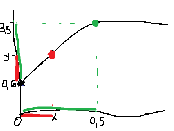
Next we have to convert the voltage to dust density according to the graph offered in the datasheet.
We have from the graph and datasheet info:
Output voltage at no dust 0.6v - 0 mg/m3 dust - given in the datasheet
And the graph intersect at 3.5v - 0.5 mg/m3 dust - you can see it on the graph clearly
With two points we can make a formula.
y-0.6 = x-0
3.5-0.6 = 0.5-0
y-0.6 3.5-0.6
------- = ----------
x-0 0.5-0
x = 0.5(y-0.6) / (3.5-0.6)
x = (y-0.6)*0.5/2.9 = (y-0.6)*0.17 = 0.17*y - 0.6*0.17 = 0.17y-0.1
Note: the sensor it is not very exact, as in the datasheet it says voltage at no dust is typical 0.6V but can go from 0.1V to 1.1V
if(output_voltage>0.6) {
dust_density = (0.1724 * output_voltage) - 0.1;
dust_density *= 1000;
}
There you go.
Because the sensor output fluctuates a lot and it is not stable, i like to make an average of around 100 reads (129 in the code below) or about one second - one read takes 10ms - so the output its a bit more stable.
Next is full code that shows result on and a lcd screen or on the serial console.
#include "LiquidCrystal_I2C.h"
LiquidCrystal_I2C lcd(0x27,20,4);
#define dustPin A0
#define ledPin 2
void setup() {
lcd.init(); // initialize the lcd
lcd.backlight();
lcd.clear();
Serial.begin(115200);
while (!Serial) delay(100);
Serial.println("GP2Y1010AU0F Sensor demo");
pinMode(ledPin,OUTPUT);
}
int i =0;
float sum =0;
void loop() {
float output_voltage =0;
float dust_density = 0;
// 100 samples medie - 1 reading per second
// one read
digitalWrite(ledPin, LOW); // power on the LED
delayMicroseconds(280); // Wait 0.28ms according to DS
output_voltage = analogRead(dustPin);
delayMicroseconds(40);
digitalWrite(ledPin, HIGH); // turn the LED off
output_voltage = (3.33 / 4096) * output_voltage; // max 3.6v
delayMicroseconds(9760);
if(output_voltage>0.6) {
dust_density = (0.1724 * output_voltage) - 0.1;
dust_density *= 1000;
}
else dust_density = 0;
sum = sum + dust_density;
i++;
if(i==129*2) {
dust_density = sum / i;
i=0;
sum =0;
lcd.setCursor(0,0);
lcd.print("Dust: ");
lcd.setCursor(6,0);
lcd.print(dust_density);
lcd.print("ug/m3");
/*
Serial.print(",\tDust Density = ");
Serial.print(dust_density);
Serial.println(" ug/m3");
*/
}
}